English

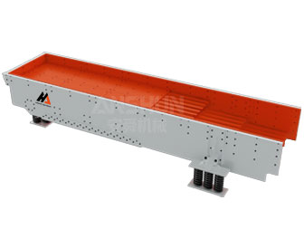
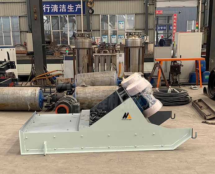
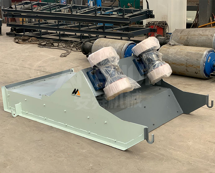
SP Suspended Vibrating Feeder
Model: SP Series · Feeding · Rock & Ore
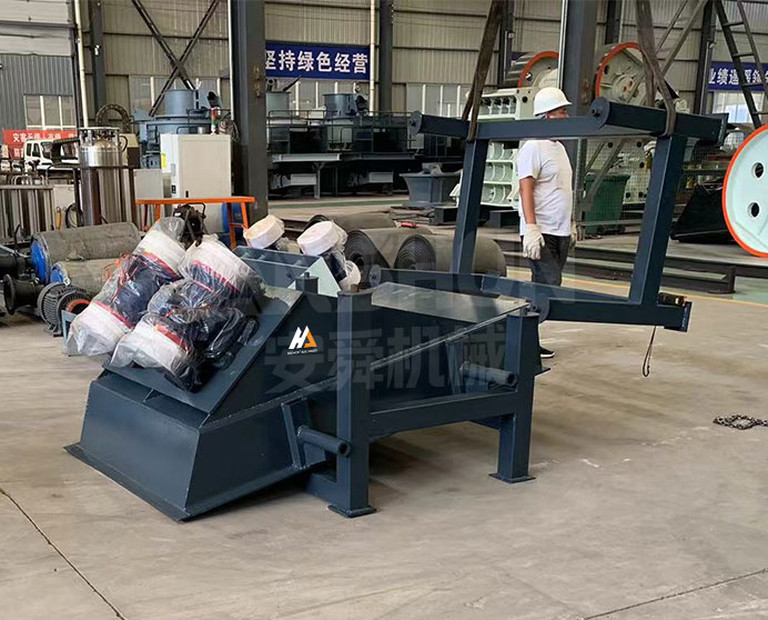
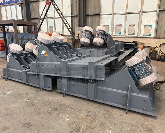
-
Funnel Width
1000–1200 mm
-
Capacity
150–400 t/h
-
Power
2.2–3.0 kw
- ISO9001
- CE
- EAC
We reply within 24 hours
Product Overview
What Is a Suspended Vibrating Feeder?
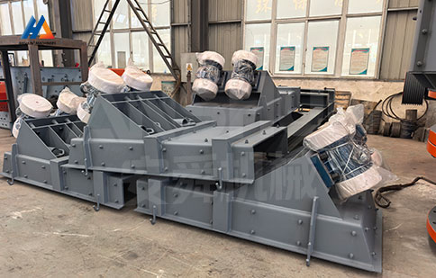
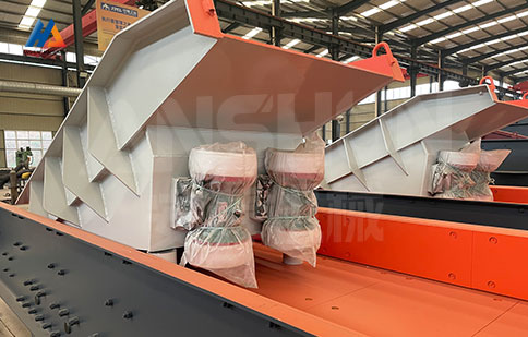
The SP suspended vibrating feeder is a linear-motion trough feeder that uses twin vibration motors as its excitation source and hangs from the support structure on flexible suspension elements rather than resting on a rigid base. This suspended mounting configuration prevents the trough’s operating vibration from being transmitted into the supporting steelwork or concrete – a critical requirement for installations on upper floors, mezzanine platforms, and structures that also carry weighing or instrumentation equipment sensitive to structure-borne vibration.
Material placed in the trough is advanced toward the discharge end by the linear reciprocating motion of the trough body, produced by the counter-rotating out-of-balance masses of the two vibration motors. Feed rate is stable, continuous, and adjustable through the motor excitation setting or – with an optional variable-frequency drive – through proportional speed control. The SP series is widely used in metallurgy, mining, coal, power, building materials, chemicals, and mechanical-engineering industries as the standard feed unit for vibrating conveyors, vibrating screens, bucket elevators, crushers, and automated batching and packaging lines.
Applicable Materials
Limestone, Granite, Basalt, Coal, Coke, Clinker, Gypsum, Salt, Granular chemicals, Slag, Sand & gravel, Ceramic raw materials, Fertilizer, Grain (non-food contact industrial grade)
Industries
Metallurgy, Mining, Coal Preparation, Electric Power, Building Materials, Chemical Processing, Mechanical Engineering, Aggregate & Concrete Production, Automated Batching & Packaging
Technical Specifications
|
Model |
Size of Funnel(mm) |
Capacity(t/h) |
Power(kw) |
|
SP1000 |
1000*2000mm |
150-200t/h |
1.1*2=2.2kw |
|
SP1220 |
1200*2000mm |
300-400t/h |
1.5*2=3kw |
Key Features & Advantages
-
Twin-Shaft Gearbox Exciter - Synchronised Dual-Axis Drive
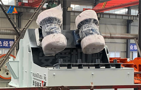
The ZSW uses a twin-shaft gearbox-type exciter in which two eccentric shafts are coupled by precision-cut helical gears inside a sealed housing. The gear transmission forces both shafts to rotate in strict counter-phase synchronisation at all times, ensuring the resultant linear excitation force remains consistently directional and eliminates the amplitude instability and phase drift that occur with independently-mounted dual-motor arrangements. The sealed gearbox also protects the exciter internals from dust and moisture ingress in outdoor quarry and mine environments.
-
Q245R Boiler-Grade Side Plates & Reinforcement Panels
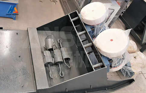
Both side plates and all reinforcement panels are fabricated from Q245R pressure-vessel (boiler) steel rather than the Q235 mild steel used in standard-grade feeders. Q245R has a minimum yield strength of 245 MPa and significantly higher notch toughness and resistance to crack propagation than Q235. Under the sustained high-cycle fatigue loading of continuous heavy-duty feeding - particularly where dump trucks discharge directly into the hopper - this material choice prevents the progressive plate tearing and side-plate cracking that is the dominant structural failure mode on competing machines.
-
Q345 Manganese-Steel Liner Plates & Floor Plate
The trough floor and all internal wear-contact surfaces are lined with Q345 manganese steel plate rather than standard carbon steel. Manganese steel work-hardens progressively under repeated impact and abrasion, developing a hard surface layer while retaining a tough, crack-resistant core. The result is a liner life two to three times that of plain carbon-steel lining on hard-rock feeds such as granite and basalt, reducing the frequency and cost of liner replacement shutdowns over the machine's service life.
-
3–8° Adjustable Installation Slope - Wet and Dry Material Compatible
The ZSW is rated for installation slopes from 3° to 8° (downward toward discharge), covering both the standard dry-aggregate feed configuration and the steeper angles required for wet, sticky, or high-moisture feeds. A 3–5° slope suits dry limestone, granite, and gravel where a gentle gravity assist maintains conveying velocity without surge. A 5–8° slope is recommended for moist coal, clay-bearing ore, and water-saturated river gravel, where the steeper angle prevents material from stalling on the trough floor and building up against the feed gate. No structural alteration is required to change the slope within this range - the mounting feet incorporate slotted bolt holes for on-site angle adjustment.
What Is the Working Principle of the SP Suspended Vibrating Feeder?
Two vibration motors are mounted symmetrically on the trough body with their shaft axes parallel and their eccentric masses set to rotate in opposite directions at the same angular velocity. At any instant, the horizontal components of the two centrifugal forces cancel while the vertical components in the feed direction add together, producing a net linear force that alternately accelerates and decelerates the trough along a straight line angled at approximately 30° to the trough floor. This linear excitation force causes the trough to oscillate back and forth along that direction at the motor's operating frequency (typically 50 Hz, corresponding to 3000 rpm for two-pole motors).
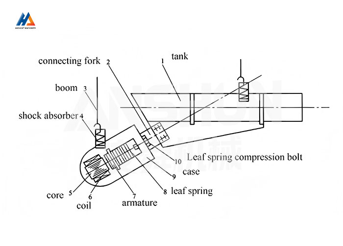
Material resting on the trough floor experiences the same oscillation. On the forward stroke - toward the discharge end - the trough accelerates beneath the material faster than gravity can keep the material in contact with the floor, causing the material to briefly leave the surface and project forward. On the return stroke, the trough decelerates and moves back while the material continues forward under inertia. The net result is that material advances in a series of small hops toward the discharge end at a rate controlled by the vibration amplitude. The suspension elements - rubber cords or coil springs connecting the trough frame to the overhead structure - absorb the residual reaction force before it reaches the support, decoupling the vibrating mass from the structure and isolating it from sensitive downstream instrumentation.
Get QuoteFAQ
What installation angle is recommended for the SP series?
For batching, proportioning, and automatic-control applications, horizontal installation (0°) is recommended to ensure uniform, gravity-independent feed rate and to prevent uncontrolled material flow when the motors are stopped. For general continuous feeding applications where a slight gravity assist is acceptable, a downward slope of up to 5–8° increases conveying velocity and is preferred for dry, free-flowing materials. For sticky or high-moisture materials, a downward slope of 5–10° is recommended to assist discharge and prevent build-up on the trough floor.
How is the feed rate adjusted on an SP vibrating feeder?
Feed rate is adjusted by changing the vibration amplitude via the excitation mass setting on the vibration motors. Most SP motor configurations allow the eccentric mass position to be adjusted in discrete steps at the motor end, increasing or decreasing the resultant force and therefore the trough amplitude. For continuous variable control – required in automatic proportioning systems – a variable-frequency drive (VFD) on the motor supply adjusts motor speed, which directly and linearly controls amplitude and feed rate. VFD control is available as an option on all SP models.
Can the SP series handle wet or sticky materials?
Yes, with appropriate installation angle and trough lining. For materials with moisture content above 8–10% or with cohesive properties (fine limestone, moist coal, clay-bearing ore), specify a downward installation slope of 5–10° and a smooth-surface trough lining – either polished stainless steel or polyurethane – to minimize adhesion. For extremely cohesive materials above 15% moisture, combine the SP with an air-knife or vibrating-pad anti-build-up system on the trough underside.
Is On-site Commissioning Support Available?
Remote commissioning support via video call is included at no charge. On-site engineer dispatch is available as an optional paid service — lead time and cost depend on location. Please discuss before purchase.