English

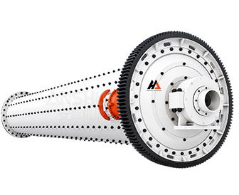
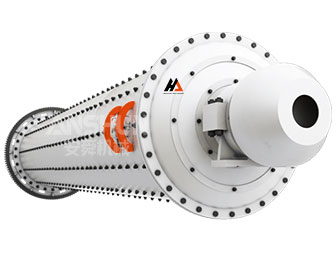
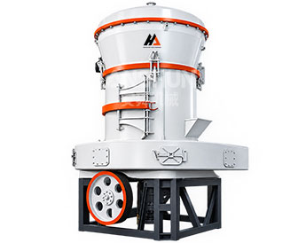
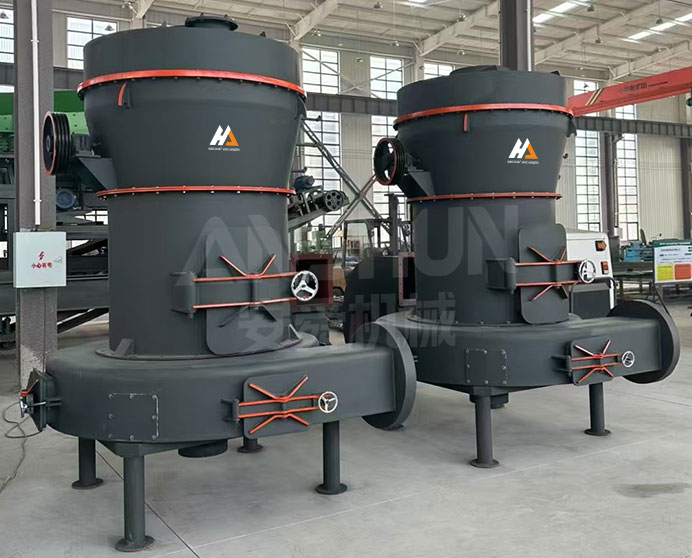
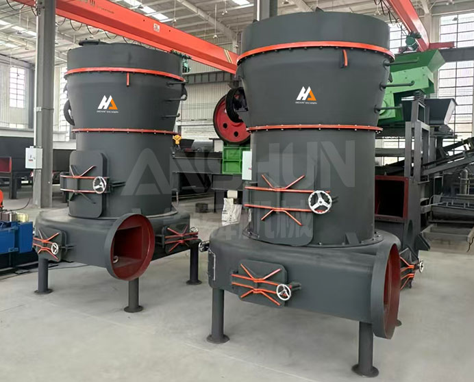
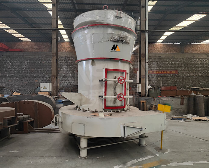
Raymond Mill
Model: Raymond Series · Grinding · Non-metallic Minerals
-
Feed Size
<35mm
-
Capacity
1-50t/h
-
Power
4-160kw
- ISO9001
- CE
- EAC
We reply within 24 hours
Product Overview
What Is a Raymond Mill?
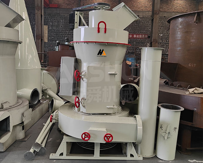
The Raymond mill is a roller-and-ring grinding mill used to reduce non-metallic mineral feed to fine powder in the 0.044–0.125 mm (125–325 mesh) range. Feed material is crushed and ground between rotating rollers and a stationary grinding ring under spring-applied pressure, while an integrated air classifier separates correctly-sized particles for collection and returns oversize particles to the grinding chamber for further reduction. The closed-circuit air conveying system transports ground material from the mill to the cyclone collector, minimizing fine-particle dust emission.
Eight standard frame sizes cover feed lump sizes from 5–8 mm (3R6010) up to 35 mm (6R4830), and capacities from 1 t/d for small-batch or laboratory production to 50 t/d for continuous industrial powder production. The 3or4R9716 and 3or4R9918 frames are available in 3-roller or 4-roller configurations, providing a capacity step within a single frame footprint. The Raymond mill is the standard fine-powder grinding solution for non-metallic minerals across the construction-materials, chemical, and industrial-mineral industries.
Applicable Materials
Limestone, Calcite, Gypsum, Barite, Dolomite, Talc, Marble, Kaolin, Bentonite, Feldspar, Quartz (low-hardness grades), Activated carbon, Coal (non-explosive grades)
Industries
Building Materials (putty powder, dry-mix mortar, plasterboard), Chemical Industry, Metallurgy & Industrial Minerals, Coal Powder Production, Oilfield Drilling-Fluid Additives, Agricultural & Feed Additives
Technical Specifications
|
Model Parameters |
3R6010 |
3R7616 |
3R7816 |
3R8817 |
3or4R9716 |
3or4R9918 |
5R4123 |
6R4830 |
|
Maximum Feed Size |
5-8mm |
15mm |
20mm |
22mm |
25mm |
25mm |
30mm |
35mm |
|
Finished Particle Size |
0.125-0.044 |
0.125-0.044 |
0.125-0.044 |
0.125-0.044 |
0.125-0.044 |
0.125-0.044 |
0.125-0.044 |
0.125-0.044 |
|
Capacity(t/d) |
1-4 |
2-6 |
2-8 |
3-12 |
4-15 |
5-20 |
6-40 |
10-50 |
|
Center Shaft Speed |
280 |
150 |
150 |
150 |
140 |
140 |
103 |
82 |
|
Roller Diameter(mm) |
150 |
260 |
270 |
300 |
320 |
310 |
410 |
480 |
|
Roller And Griding Ring Height(mm) |
100 |
160 |
160 |
170 |
160 |
180 |
230 |
300 |
|
Main Motor(Kw) |
6-7.5kw |
8-18.5kw |
8-22kw |
8-30kw |
4-37kw |
8-37kw |
4-75kw |
4-160kw |
|
Fan Motor(Kw) |
4-7.5kw |
4-18.5kw |
4-22kw |
4-30kw |
4-30kw |
4-37kw |
4-90kw |
4-160kw |
|
Motor Analyzer(Kw) |
6-1.1kw |
6-2.2kw |
6-2.2kw |
6-2.2kw |
4A-7.5kw |
6-7.5kw |
4B-11kw |
4B-22kw |
|
Installation Dimensions(m) |
3.34*2.161*3.246 |
4.65*3.30*4.5 |
4.60*3.40*4.80 |
5.00*4.50*5.20 |
8.50*5.80*8.00 |
7.50*5.80*9.00 |
10.00*11.00*7.00 |
10.00*11.00*9.00 |
Key Features & Advantages
-
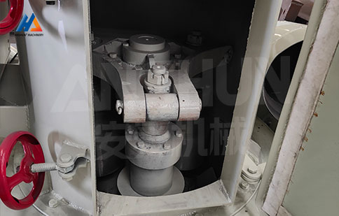
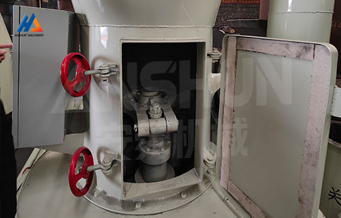
Roller-and-Ring Grinding with Spring Pressurization
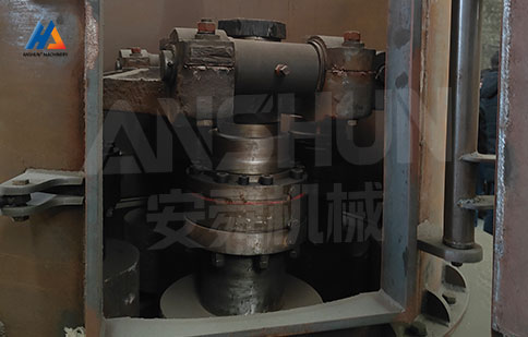
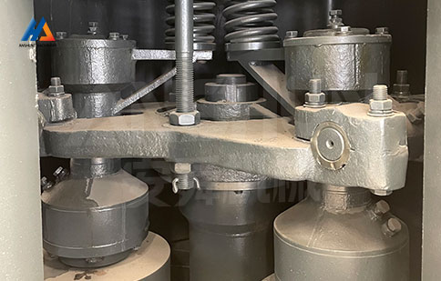
Each grinding roller is pressed against the grinding ring by a high-tension spring assembly, providing consistent, adjustable grinding force independent of feed-rate fluctuation. As the main shaft rotates, centrifugal force swings the rollers outward against the ring while the spring maintains contact pressure, crushing and grinding material between the roller and ring surfaces into fine powder.
-
Integrated Classifier - Single-Pass Particle Sizing
An air classifier mounted above the grinding chamber returns oversize particles to the grinding zone for further reduction while allowing correctly-sized particles to pass to the cyclone collector. The analyzer (classifier) motor speed is independently adjustable, allowing the finished particle size to be tuned within the 0.044–0.125 mm range without changing the roller-ring assembly.
-
Eight Frame Sizes, 1–50 t/d
The R series covers eight standard frame sizes from 3R6010 (1–4 t/d, suited to laboratory and small-batch production) to 6R4830 (10–50 t/d, suited to continuous industrial mineral powder production). The 9716 and 9918 frames are available in 3-roller or 4-roller configurations, allowing capacity to be matched within a frame size without selecting a different base machine.
-
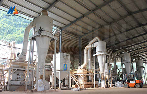
Closed-Circuit Air System - Low Dust Emission
Material is conveyed through the mill, classifier, and cyclone collector by a closed-loop air circuit driven by the fan (blower) motor. Fine product settles out in the cyclone while the circulating air returns to the mill housing; only a small bleed stream passes through the dust collector before discharge. This closed-circuit design keeps workplace dust levels low and reduces fine-product loss to atmosphere compared to open-circuit milling systems.
-
Wear-Resistant Roller and Ring Materials
Grinding rollers and rings are manufactured from high-chromium cast iron or alloy steel selected according to the abrasiveness of the feed material. For non-metallic minerals such as limestone, calcite, and gypsum, standard alloy rollers provide long service life; for more abrasive materials such as barite or dolomite with higher silica content, high-chromium rollers are recommended to extend the interval between roller and ring replacements.
What Is the Working Principle of the Raymond Mill?
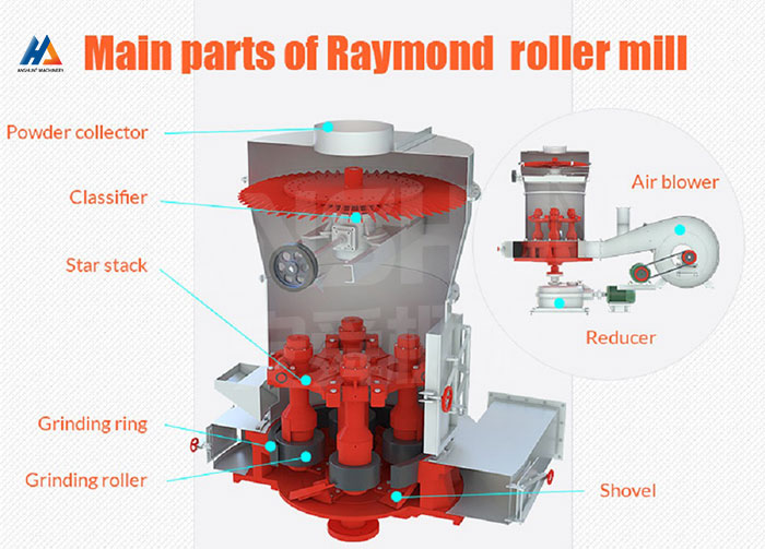
Feed material enters the grinding chamber through the feed inlet and falls onto the grinding ring. The main shaft, driven by the main motor through a gearbox, rotates the roller assembly. Centrifugal force generated by rotation swings each grinding roller outward against the inner surface of the grinding ring, while a pre-tensioned spring assembly applies additional pressure to the roller. Material trapped between the roller and ring surfaces is crushed and ground by the combined rolling and pressing action as the rollers sweep around the ring.
Ground material is lifted by the air current generated by the fan (blower) motor and carried upward into the classifier housing above the grinding chamber. The rotating classifier blades, driven by the analyzer motor, create a centrifugal separation zone: particles coarser than the target size are rejected by the classifier and fall back into the grinding chamber for further grinding, while correctly-sized particles pass through the classifier with the air stream to the cyclone collector. In the cyclone, the fine powder separates from the air stream by centrifugal settling and discharges through the cyclone underflow as the finished product, while the air returns to the mill housing via the closed-circuit duct, completing the air loop.
Get QuoteFAQ
What is the difference between the 3-roller and 4-roller configurations on the 9716 and 9918 frames?
Both configurations share the same mill housing, main shaft, and classifier. A 4-roller configuration adds one additional grinding roller and ring set around the main shaft, increasing the grinding surface area in contact with the material at any instant. This raises throughput by approximately 25–30% within the same frame footprint at a modest increase in main-motor power draw. The 3-roller configuration is suitable where the lower end of the capacity range is sufficient; the 4-roller configuration is selected when maximum throughput from a given frame size is required.
Can the finished particle size be adjusted without changing the rollers?
Yes, within the 0.044–0.125 mm (125–325 mesh) range, finished particle size is primarily controlled by the analyzer (classifier) motor speed. Increasing classifier speed returns more material to the grinding zone for further reduction, producing a finer finished product; decreasing classifier speed allows coarser material to pass, increasing throughput at a coarser particle size. For target particle sizes outside this range, consult us regarding alternative roller and ring geometry.
How is the correct frame size selected for a given application?
Frame selection depends on three factors: required daily capacity (t/d), maximum feed lump size, and material hardness/abrasiveness. As a starting point, match your required capacity to the t/d range in the specification table – but note that capacity is also affected by material hardness (the t/d figures are typically based on materials with a Mohs hardness below 6 such as limestone and gypsum) and target fineness (finer target particle sizes reduce throughput within a given frame). For harder materials (Mohs 6–7, such as quartz or barite) or very fine target particle sizes, select one frame size larger than the capacity table would suggest, or consult us with your feed data for a confirmed recommendation.
Is On-site Commissioning Support Available?
Remote commissioning support via video call is included at no charge. On-site engineer dispatch is available as an optional paid service — lead time and cost depend on location. Please discuss before purchase.