English

Ball Mill
Model: Ball Mill Series · Grinding · Ore & Minerals
-
Feed Size
≤25mm
-
Capacity
0.65-130 t/h
-
Power
18.5-800kw
- ISO9001
- CE
- EAC
We reply within 24 hours
Product Overview
What Is a Ball Mill?
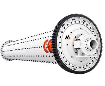
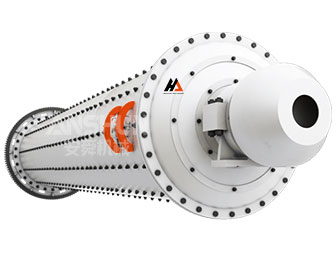
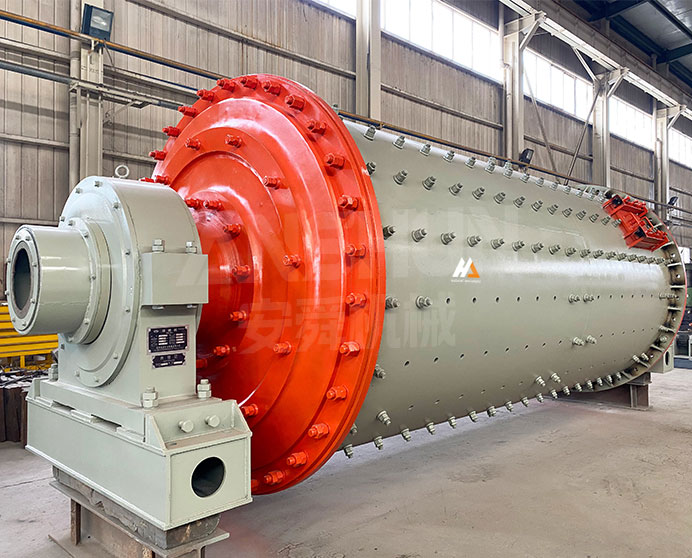
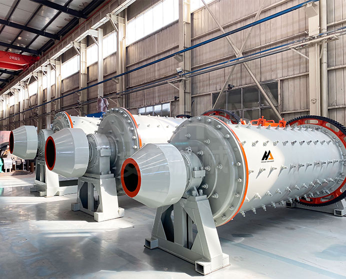
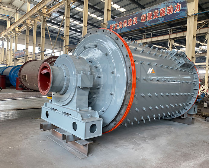
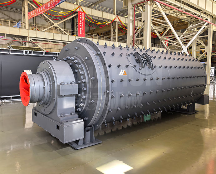
The ball mill is a horizontal rotating cylindrical mill that uses steel balls as the grinding medium to reduce crushed ore and other materials to a fine powder suitable for flotation, leaching, or further mineral processing. Feed material enters one end of the rotating shell together with the steel ball charge; as the shell rotates, the balls are lifted and cascade, repeatedly impacting and abrading the material between them and against the wear-resistant shell liners until it is reduced to the target particle size and discharges at the opposite end.
Twenty-four standard models cover shell diameters from φ900 mm to φ3200 mm and lengths from 1800 mm to 7500 mm, providing capacities from 0.65 t/h (φ900×1800) to 130 t/h (φ3200×4500). All models accept feed up to 25 mm (or 20 mm for the smallest φ900 models) and produce output in the 0.074–0.89 mm range. The ball mill is the standard primary or secondary grinding unit in metal-ore concentrators, non-metallic mineral processing, and chemical and ceramic raw-material preparation.
Applicable Materials
Gold ore, Copper ore, Iron ore, Lead-zinc ore, Manganese ore, Chrome ore, Antimony ore, Limestone, Quartz, Feldspar, Cement clinker, Slag, Ceramic raw materials, Refractory materials
Industries
Metal Ore Mining & Concentration, Non-Metallic Mineral Processing, Cement Production, Chemical Industry, Ceramics & Refractory Materials, Power Plant Coal Grinding (FGD limestone), Building Materials
Technical Specifications
|
Ball Mill Technical Parameters |
|||||||
|
Model |
Rotary Speed |
Ball Load |
Input Size(mm) |
Output Size(mm) |
Capacity |
Power |
Weight |
|
φ900x1800 |
36-38 |
1.5 |
≤20 |
0.075-0.89 |
0.65-2 |
18.5 |
4.6 |
|
φ900x3000 |
36 |
2.7 |
≤20 |
0.075-0.89 |
1.1-3.5 |
22 |
5.6 |
|
φ1200x2400 |
36 |
3 |
≤25 |
0.075-0.6 |
1.5-4.8 |
30 |
12 |
|
φ1200×3000 |
36 |
3.5 |
≤25 |
0.074-0.4 |
1.6-5 |
37 |
12.8 |
|
φ1200x4500 |
32.4 |
5 |
≤25 |
0.074-0.4 |
1.6-5.8 |
55 |
13.8 |
|
φ1500x3000 |
29.7 |
7.5 |
≤25 |
0.074-0.4 |
2-5 |
75 |
15.6 |
|
φ1500 x4500 |
27 |
11 |
≤25 |
0.074-0.4 |
3-6 |
90 |
21 |
|
φ1500x5700 |
28 |
12 |
≤25 |
0.074-0.4 |
3.5-6 |
130 |
24.7 |
|
φ1830x3000 |
25.4 |
11 |
≤25 |
0.074-0.4 |
4-10 |
130 |
28 |
|
φ1830×4500 |
25.4 |
15 |
≤25 |
0.074-0.4 |
4.5-12 |
155 |
32 |
|
φ1830×6400 |
24.1 |
21 |
≤25 |
0.074-0.4 |
6.5-15 |
180 |
34 |
|
φ1830x7000 |
24.1 |
23 |
≤25 |
0.074-0.4 |
7.5-17 |
210 |
36 |
|
φ2100x3000 |
23.7 |
15 |
≤25 |
0.074-0.4 |
6.5-36 |
210 |
34 |
|
φ2100 x4500 |
23.7 |
24 |
≤25 |
0.074-0.4 |
8-43 |
245 |
42 |
|
φ2100×7000 |
23.7 |
26 |
≤25 |
0.074-0.4 |
8-48 |
280 |
50 |
|
φ2200×3600 |
21.5 |
27 |
≤25 |
0.074-0.4 |
9-40 |
280 |
50 |
|
φ2200×4500 |
21.5 |
27 |
≤25 |
0.074-0.4 |
9-45 |
280 |
48.5 |
|
φ2200x6500 |
21.7 |
35 |
≤25 |
0.074-0.4 |
14-26 |
370 |
52.8 |
|
φ2200x7000 |
21.7 |
35 |
≤25 |
0.074-0.4 |
15-28 |
380 |
54 |
|
φ2200x7500 |
21.7 |
35 |
≤25 |
0.074-0.4 |
15-30 |
380 |
56 |
|
φ2400x3000 |
21 |
23 |
≤25 |
0.074-0.4 |
8.5-55 |
320 |
60 |
|
φ2400x4500 |
21 |
28 |
≤25 |
0.074-0.4 |
8.5-60 |
320 |
65 |
|
φ2700×4000 |
20.7 |
30 |
≤25 |
0.074-0.4 |
12-80 |
400 |
94 |
|
φ2700x4500 |
20.7 |
48 |
≤25 |
0.074-0.4 |
16-90 |
430 |
102 |
|
φ3200x4500 |
18 |
65 |
≤25 |
0.074-0.4 |
25-130 |
800 |
137 |
Key Features & Advantages
-
Steel Grinding Media in Rotating Cylindrical Shell
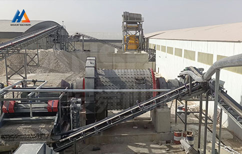
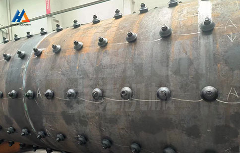
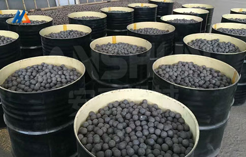
The ball mill consists of a horizontal cylindrical shell, partially filled with steel grinding balls, that rotates about its axis. As the shell rotates, the ball charge is lifted and tumbles, repeatedly impacting and grinding feed material trapped between balls and against the shell liner. Ball load (1.5 t to 65 t across the range) is selected based on shell volume and target grind, and is topped up periodically as balls wear.
-
Twenty-Four Standard Models, 0.65–130 t/h
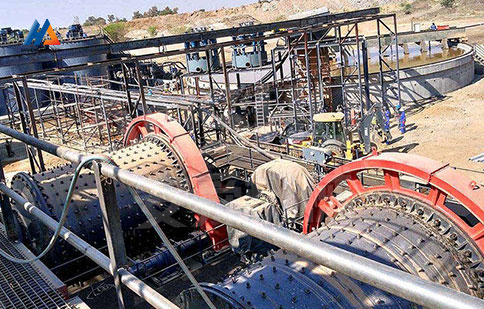
The series covers shell diameters from φ900 mm to φ3200 mm and lengths from 1800 mm to 7500 mm, providing twenty-four combinations of capacity (0.65–130 t/h) and grinding fineness (0.074–0.89 mm) to match feed material, target output size, and required throughput across small mineral-processing operations through to large concentrator plants.
-
Wear-Resistant Liner Plates
The internal shell surface is fitted with replaceable manganese-steel or high-chromium liner plates, selected according to feed abrasiveness. Liners both protect the shell from direct impact wear and shape the lifting action of the ball charge - different liner profiles (wave, ripple, or smooth) are available to optimize grinding efficiency for specific ore types and target particle sizes.
-
Low-Speed Trunnion Bearing Support
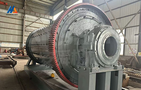
The mill shell is supported on two trunnion bearings at either end, allowing the heavy rotating mass to turn with low friction at the relatively slow rotary speeds shown in the specification table (18–38 rpm depending on model - larger mills rotate more slowly). Sliding-shoe or roller-bearing trunnion support options are available depending on mill size and site maintenance preference.
-
Wide Output Range - 0.074 to 0.89 mm
Output particle size is controlled primarily by ball charge gradation (the mix of large and small ball diameters), rotation speed, and residence time (controlled by feed rate and discharge configuration). The φ900×1800 and φ900×3000 models can target the coarser 0.075–0.89 mm range for primary grinding ahead of further processing, while all other models target the finer 0.074–0.4 mm range typical of flotation feed preparation.
What Is the Working Principle of the Ball Mill?
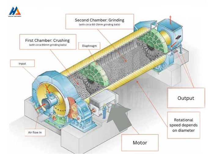
Crushed feed material (≤25 mm) enters the mill shell through a feed trunnion at one end, together with the steel ball charge already present in the shell. The shell, supported on trunnion bearings at both ends, is rotated by the main motor through a gear-and-pinion or direct-drive transmission at the rotary speed shown in the specification table - larger-diameter shells rotate more slowly to maintain the correct ball-cascading action at their critical speed fraction.
As the shell rotates, friction between the shell liner and the ball charge lifts the balls along the rising side of the shell to an angle where gravity overcomes the lifting force, causing the balls to cascade and tumble down through the material bed. This combined impact-and-attrition action repeatedly fractures feed particles trapped between balls and between balls and the liner. Material progressively moves along the shell length from the feed end to the discharge end under the combined action of the slight shell slope (where present) and the bulk flow of new feed entering behind it. At the discharge end, ground material exits through a discharge trunnion or grate, either as the final product (open circuit) or to a classifier for size separation and return of oversize material to the mill (closed circuit).
Get QuoteFAQ
How is the correct ball mill model selected for a given application?
Model selection depends on required throughput (t/h), target output particle size, feed hardness (work index), and feed top size after primary crushing (typically ≤25 mm for this series). As a starting point, match required throughput to the capacity range in the specification table at the target output size band (0.074–0.4 mm for most models, 0.075–0.89 mm for the smaller φ900 models). Note that the stated capacity ranges assume moderate-hardness ores; for harder feed materials (higher Bond work index), select one size larger, or provide your ore’s work index and required P80 grind size for a confirmed recommendation based on grinding-circuit calculations.
What determines the ball charge size and how often does it need topping up?
Ball load (shown in the specification table) is the total mass of steel grinding balls in the mill at normal operating fill level – typically 30–35% of internal mill volume. Balls wear at a rate dependent on feed abrasiveness, ball hardness, and mill operating parameters; typical wear rates range from 0.5–1.5 kg of steel consumed per tonne of ore processed for moderate-abrasion materials. Mills are topped up with new balls on a regular schedule (often weekly or monthly depending on throughput) to maintain the target ball charge mass and size distribution, since larger balls wear down into smaller sizes that contribute to the overall grinding action until they are eventually discharged or screened out.
What is the difference between open-circuit and closed-circuit operation?
In open-circuit operation, material passes through the mill once and the discharge is the final product – simple to operate but typically produces a wider particle-size distribution with some over-ground and under-ground material. In closed-circuit operation, mill discharge is fed to a classifier (hydrocyclone or spiral classifier); correctly-sized material proceeds to the next process step while oversize material is returned to the mill for further grinding. Closed-circuit operation produces a tighter, more controlled particle-size distribution and is the standard configuration for flotation feed preparation, though it requires the additional classifier equipment and associated pumping.
Is On-site Commissioning Support Available?
Remote commissioning support via video call is included at no charge. On-site engineer dispatch is available as an optional paid service — lead time and cost depend on location. Please discuss before purchase.